1-800-355-2335 |
Mon-Fri: 7:30am - 4pm EST |
Contact Us

Security Brands Advantage DKLP - Model 19-100i - Intercom/Keypad (100 code)
Item # 19-100i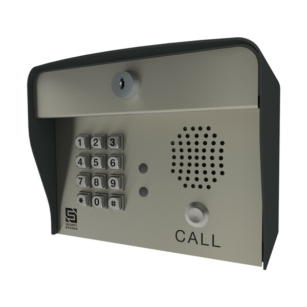
Details
Details
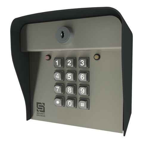
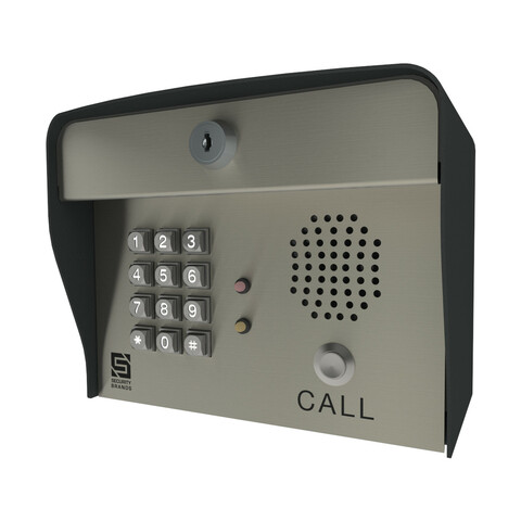
Advantage DKLP - Model 19-100i - Intercom/Keypad
Introduced for the solar gate opener, the DKLP series is designed for the user who has need for a LOW POWER application. Boasting a power consumption of under 20uA, the Advantage DKLP line of keypads is the industry leader for solar applications. No night light available.
No-nonsense Operation: If you’re looking for a keypad that is easy to program and easy to use, look no further!
Goes Where You Go: With such a low current draw, this unit can be located in the remotest of locations, as long as sunlight is sufficient.
Sturdy & Durable: Crafted exclusively from stainless and powder-coated steel, this box is built to last!
Programming You Know: Quick, simple, and familiar, the basic programming steps on the keypad are identical to those on all of our keypads.
Features:- Stainless steel face plate and metal keypad offer offer extra strength and help protect against vandalism
- 5.25" high x 7.75" wide x 4.5" deep
- Operates using less than 20 uA @ 12 VDC with plug-in transformer. (not provided)
- Non-volatile Memory
- PERFECT for SOLAR Gate Openers
- 100 four-digit code capacity
- Personal master code
- Variable Relay Time
- Relay Shunt for Alarm Sytem
- Audio-Tone Feedback
- Stand-Alone
- 2 Relays and an External Event Input
- Built in Intercom Door Station
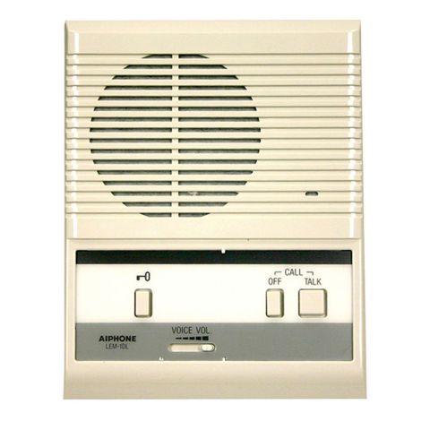
- This unit must be used with another unit for intercom. (LEM-1DL recommended)
- 2 Year Warranty
- Made in the USA from Global Materials
Specifications
Specifications
AAS Advantage DKLP - Model 19-100i - Specifications (PDF)
| Distance | Gauge Wire |
|---|---|
| Up to 150 feet | 22 gauge |
| 151 to 700 feet | 20 gauge |
| 701 to 1500 feet | 18 gauge |
| # of Stations | Maximum Cable Length |
|---|---|
| 1 Station | 600 Feet |
| 2 Stations | 300 Feet |
| 3 Stations | 160 Feet |
| 4 Stations | 80 Feet |
| Maximum number of stations per cable | 4 |
| Maximum number of stations per system | 20 |
Warranty
Warranty
AAS 2-YEAR LIMITED WARRANTY
What item(s) this warranty applies to:
American Access Systems "DKS (12-XXX Series)" access controls.
What is covered:
Any defect in materials or workmanship
For how long:
Two years from date of purchase.
What we will do:
If your AAS product is defective and returned within 2 years of the date of purchase, we will repair it or, at our option, replace it at no charge to you. If we repair your AAS product, we may use new or reconditioned parts. If we choose to replace your AAS product, we may replace it with a new or reconditioned one of the same or similar design.. The repair or replacement will be warranted for (a) 90 days or (b) the remainder of the original two year warranty period whichever is longer.
Limitations:
Implied warranties, including those of fitness for a particular purpose and merchant ability (an unwritten warranty that the product is fit for ordinary use), are limited to two years from date of purchase. We will not pay for loss of time, inconvenience, loss of use of your AAS product, service calls, or property damage caused by your AAS product or its failure to work, or any other incidental or consequential damages. Some states do not allow limitations on how long an implied warranty lasts or the exclusion or limitation of incidental or consequential damages, so the above exclusions or limitations may not apply to you.
What we ask you to do:
To get warranty service for your AAS product, you must provide proof of the date of purchase. Contact the original dealer or installer of the product and return your AAS product along with the receipt to them. if you have problems locating the dealer or installer contact American Access Systems at (303)799-9757 and we will direct you to a an authorized dealer or distributor of American Access Systems products. If you ship your AAS product, you must prepay all shipping costs. We suggest that you retain your original packing material in the event you need to ship your AAS product. On return, include your name, address, phone number, proof of date of purchase, and a brief description of the operating problem.
What this warranty does not cover:
This warranty does not cover defects resulting from accidents, damage while in transit, alterations, unauthorized repair, failure to follow instructions, misuse, fire, flood, or acts of God. Nor do we warrant your AAS product to be compatible with any particular external device or peripheral. If your warranty has expired on your AAS product or if your product is NOT covered contact your dealer or installer for advice on whether we will repair your AAS product and other repair information, including estimated repair costs and other charges. We, at our option, may replace rather than repair your AAS product with a new or similar design if the damage to the unit is severe or extensive.
This warranty is the only one we give on this product, and it sets forth all our responsibilities regarding your AAS product. There are no other express warranties.
State Law rights:
This warranty gives you specific legal rights, and you may also have other rights which vary from state to state.
Instructions
Instructions
Reviews
Reviews
There are no reviews yet. Be the first to Write a Review (requires login).
Shipping
Shipping
Shipping Expense Disclaimer: All orders are subject to confirmation. Additional shipping expenses, although rare, may apply due to weight, size, location, and/or other variables. Should your order require additional funds to cover the transportation of goods, you will be contacted prior to order processing for approval.
Parts for this product
You May Also Like