1-800-355-2335 |
Mon-Fri: 7:30am - 4pm EST |
Contact Us

Kee Klamp Overview
Shop: Kee Klamp Fittings
Sections:
- Kee Klamp Fitting Specifications
- Sizing Chart
- Beam Load Table
- Upright Load Table
- Vibration Test Report
The Kee Klamp Fitting
The simple but effective engineering principle of the Kee Klamp Fitting is the foundation of the most versatile pipe connection system available. There are many variations of fitting to suit wide-ranging applications, providing the versatility to achieve virtually any structural configuration.
Kee Klamp fittings are malleable iron castings manufactured to the requirements of ASTM A47-77-32510. A range of fittings to suit eight sizes of pipe is available. A simple hexagon key is the only tool required to create a strong, rigid joint. A recessed set screw, tightened by the hexagon key, firmly locks the pipe into the fitting. The set screw is manufactured in case hardened steel and is Kee Koat® protected against corrosion.
A Kee Klamp fitting (size 5 to 9) can support an axial load of *2000 lbs. per set screw with the set screw tightened to a torque of 29 lbs. ft. This is normally obtained when the screw is fully tightened using a ratchet wrench.
(*rating includes a safety factor)
Sizing Chart
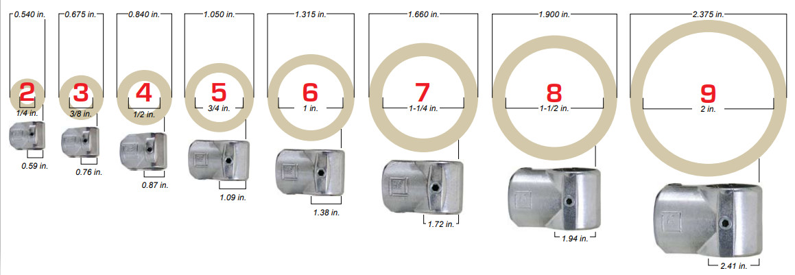
Kee Klamp steel fittings are designed to suit Schedule 40 (aluminum and steel) pipe sizes
| Kee Klamp | Tube Diameter | Nominal |
| Size | Outside Diameter (O/D) (in) |
Inside Diameter (I/D) (in) |
| 2 | 17/32" | 1/4" |
| 3 | 11/16" | 3/8" |
| 4 | 27/32" | 1/2" |
| 5 | 1" | 3/4" |
| 6 | 1-5/16" | 1" |
| 7 | 1-5/8" | 1-1/4" |
| 8 | 1-7/8" | 1-1/2" |
| 9 | 2 3/8" | 2" |
Specifying Kee Klamp Fittings
The information on fittings in this site is comprehensive, and because of the coding system we have adopted, easy to use.
Diagrams are shown for each fitting showing entry of tube/pipe, a table of dimensions and a definition of use adjacent to its appropriate Type number (10, 15, 20, 25 etc.).
Alongside the Type number is a code (4, 5, 6, 7, etc.) relating to the outside diameter of the tube/pipe for which the Kee Klamp had been designed. The relationship between the Kee Klamp tube/pipe reference and standard tube/pipe outside diameter is explained in the aforementioned chart.
Example: (1) A 10-7 is a Type 10 Kee Klamp fitting with both sockets designed to accept a tube/pipe that has an outside diameter of 42.4mm or 1-11/16" (1-1/4" Nominal Pipe Size). (2) A 25-9 is a Type 25 Kee Klamp fitting with all three sockets designed to accept a tube/pipe that has an outside diameter of 60.9mm or 2 3/8" (2" N.P.S.).
Where more than one tube/pipe reference is shown alongside a particular Type number, it indicates that the individual sockets are designed to accept different sizes of tube/pipe. In a multi-digit code number the first figure relates to the 'A' socket and the second to the 'B' socket. Example (3) A 45-76 is a Type 45 Kee Klamp fitting with 'A' socket accepting a tube/pipe that has an outside diameter of 42.4mm or 1-11/16", and a 'B' socket accepting a tube/pipe that has an outside diameter of 33.7mm or 1-11/32".
While Kee Klamp can give a general guidance relating to the use of each Kee Klamp fitting detailed in this site, the nature of the product means that the ultimate responsibility for selecting the correct fitting for an application must lie with the customer.
The customer should also ensure that the existing structure to which the Kee Klamp construction is being secured, is of sufficient strength to support both the self weight of the Kee Klamp construction and the imposed loads applied, including wind loads, snow loads, and any other superimposed loads.
Beam Load Table
For uneven load distributions or single spans, the required pipe size must be determined by standard bending moment calculations assuming a Kee Klamp joint to give a simply supported beam. The table shown below gives an indication only of the safe load uniformly distributed, in lbs., that may be carried per shelf consisting of front and back tubes when used as continuous beams. Recommended set screw torque: 29lbs./ft.
At loads greater than 2023 lbs., consideration must be given to set-screw slip.
| BEAM LOAD TABLE ( lb ) | ||||||
|---|---|---|---|---|---|---|
| KK FITTING | Size 5 | Size 6 | Size 7 | Size 8 | Size 9 | |
| SIZE OF PIPE | ¾" N.B. | 1" N.B. | 1¼" N.B. | 1½" N.B. | 2" N.B. | |
| GRADE OF MATERIAL | SCH. 40 | SCH. 40 | SCH. 40 | SCH. 40 | SCH. 40 | |
| SPAN | ||||||
| 1' | 1658 | 3123 | 5516 | 7669 | 13180 | |
| 2' | 829 | 1562 | 2758 | 3834 | 6590 | |
| 3' | 553 | 1041 | 1838 | 2556 | 4393 | |
| 3' 6" | 474 | 892 | 1576 | 2191 | 3766 | |
| 4' | 414 | 781 | 1379 | 1917 | 3295 | |
| 4' 6" | 368 | 694 | 1226 | 1704 | 2929 | |
| 5' | 332 | 625 | 1103 | 1534 | 2636 | |
| 5' 6" | 302 | 568 | 1003 | 1394 | 2396 | |
| 6' | 277 | 520 | 919 | 1278 | 2197 | |
| 6' 6" | 255 | 481 | 849 | 1180 | 2028 | |
| 7' | 237 | 446 | 788 | 1096 | 1883 | |
| 7' 6" | 221 | 417 | 735 | 1023 | 1757 | |
| 8' | 207 | 390 | 690 | 959 | 1648 | |
| 9' | 184 | 347 | 613 | 852 | 1464 | |
| 10' | 166 | 313 | 551 | 767 | 1318 | |
Upright Load Table
This table gives an indication only of the safe load, in lbs., that may be carried between the above restraints by single Schedule 40 pipe, 30000 PSI, when used as uprights. Loads listed under 'A' columns refer to those loads that are obtainable according to schematic 'B'. Schematic 'B' details a racking system that is mechanically affixed to the surface on which it stands, whereas Schematic 'A' details a free-standing racking system. Recommended screw torque: 29 lbs./ft.
| UPRIGHT LOAD TABLE ( lb ) | |||||||||||
|---|---|---|---|---|---|---|---|---|---|---|---|
| KK FITTING |
Size 5 | Size 6 | Size 7 | Size 8 | Size 9 | ||||||
| SIZE OF PIPE |
¾" N.B. | 1" N.B. | 1¼" N.B. | 1½" N.B. | 2" N.B. | ||||||
| MATERIAL GRADE |
SCH. 40 | SCH. 40 | SCH. 40 | SCH. 40 | SCH. 40 | ||||||
| Length | A | B | A | B | A | B | A | B | A | B | Length |
| 1' 0" | 1868 | 2045 | 3243 | 3390 | 4445 | 4635 | 5238 | 5403 | 7738 | 7975 | 1' 0" |
| 1' 3" | 1633 | 1855 | 2958 | 3183 | 4213 | 4445 | 4955 | 5235 | 7398 | 7635 | 1' 3" |
| 1' 6" | 1420 | 1633 | 2673 | 2958 | 3875 | 4213 | 4650 | 4955 | 7160 | 7443 | 1' 6" |
| 1' 9" | 1213 | 1493 | 2375 | 2705 | 3630 | 3948 | 4395 | 4730 | 6785 | 7160 | 1' 9" |
| 2' 0" | 995 | 1283 | 2108 | 2480 | 3335 | 3715 | 4138 | 4500 | 6448 | 6843 | 2' 0" |
| 2' 3" | 840 | 1058 | 1813 | 2245 | 3048 | 3470 | 3883 | 4268 | 6210 | 6685 | 2' 3" |
| 2' 6" | 700 | 953 | 1583 | 2020 | 2753 | 3273 | 3570 | 4003 | 5848 | 6355 | 2' 6" |
| 2' 9" | 603 | 823 | 1395 | 1780 | 2505 | 2993 | 3243 | 3730 | 5575 | 6063 | 2' 9" |
| 3' 0" | N/A | 700 | 1220 | 1583 | 2170 | 2703 | 2985 | 3523 | 5180 | 5835 | 3' 0" |
| 3' 3" | N/A | 635 | 1078 | 1435 | 1993 | 2563 | 2698 | 3283 | 4863 | 5520 | 3' 3" |
| 948 | 1288 | 1810 | 2283 | 2418 | 3083 | 4525 | 5270 | 3' 6" | |||
| N/A | 1160 | 1643 | 2085 | 2250 | 2858 | 4218 | 4978 | 3' 9" | |||
| N/A | 1025 | 1488 | 1938 | 2065 | 2603 | 3880 | 4818 | 4' 0" | |||
| 1313 | 1783 | 1880 | 2393 | 3675 | 4503 | 4' 3" | |||||
| 1215 | 1643 | 1698 | 2225 | 3303 | 4218 | 4' 6" | |||||
| N/A | 1488 | 1560 | 2098 | 3123 | 3958 | 4' 9" | |||||
| N/A | 1363 | 1450 | 1920 | 2918 | 3675 | 5' 0" | |||||
| N/A | 1270 | N/A | 1785 | 2693 | 3415 | 5' 3" | |||||
| N/A | 1698 | 2523 | 3268 | 5' 6" | |||||||
| N/A | 1520 | 2398 | 3088 | 5' 9" | |||||||
| N/A | 1450 | 2150 | 2918 | 6' 0" | |||||||
| 2048 | 2715 | 6' 3" | |||||||||
| 1878 | 2578 | 6' 6" | |||||||||
| N/A | 2398 | 6' 9" | |||||||||
| N/A | 2263 | 7' 0" | |||||||||
| N/A | 2150 | 7' 3" | |||||||||
| N/A | 2048 | 7' 6" | |||||||||
| Table reflects a safety factor or 2:1 | N/A | 1913 | 7' 9" | ||||||||
Vibration Test Report
TEST REPORT: Vibration of Kee Klamp Assemblies:
Exhaustive tests on samples of standard size 7 Kee Klamp fittings were performed by an independent research laboratory. The purpose of the test was to evaluate the use of either standard set-screws or self-locking set screws.
Test Arrangement:
A "Tee" section test assembly was made using three 300mm lengths of galvanized 1-¼" standard pipe held together by a socket Tee fitting (Type 25-7). The vertical leg of the test assembly was supported in a standard railing flange (Type 62-7). The completed assembly was then rigidly attached to the vibration table.
The test assembly was initially assembled using standard set screws and tested in the configuration. The standard set screws were then replaced with self-locking set screws and the tests repeated.
Test Procedure:
The test was conducted on a Ling 667 kg Electromagnetic vibration table.
The table was programmed to perform a resonance search between 25 and 350 Hz. The following table details the resonant frequencies that were recorded.
During the resonance search amplification factors, Q, were measured at each resonant frequency, the point of reference being the end of one horizontal pipe. The table was then held at one of the resonant frequencies, set in motion with a controlled acceleration level of 4g, and run for a period of six hours. This was repeated for three more resonant frequencies in descending order of "Q" factor.
Resonance |
||
| Frequencies | Q Factor | Running Time |
| 74 | 1.27 | Nil |
| 106 | 1.27 | Nil |
| 158 | 1.53 | 6 hours |
| 200 | 1.8 | 6 hours |
| 221 | 5 | 6 hours |
| 295 | 9 | 6 hours |
During the twenty-four hours of vibration at the four resonant frequencies above no signs of loosening with either type of set screw occurred.