1-800-355-2335 |
Mon-Fri: 7:30am - 4pm EST |
Contact Us

EMX Multi-Voltage Vehicle Loop Detector
Item # EMX-MVP-D-TEK

Details
Details
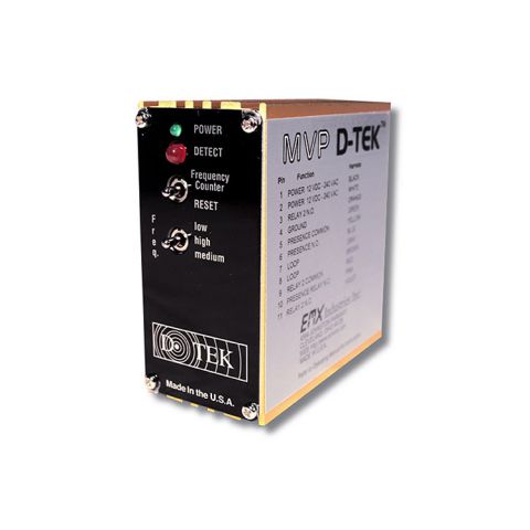
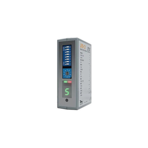
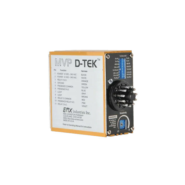
EMX Multi-Voltage Vehicle Loop Detector (MVP-D-TEK)
The MVP D-TEK multi-voltage vehicle detector makes it simple to manage your stock. All you need is one detector in your stock room and on your truck. This multi-voltage vehicle detector solves the problem of not knowing which voltage to take for service a call or installation. Reduce the cost of inventory by stocking only one loop detector – with the universal voltage of our MVP D-TEK.
- MVP-D-TEK Features:
- Universal voltage
- Reduced inventory costs
- Operates in both fail safe and fail secure modes
- Reliability
- Multi-voltage power 12 to 220 VAC/DC
- Operates in both fail safe and fail secure modes
- 10 sensitivity settings
- Enhanced lightning/surge immunity
- Aluminum RF shield housing
- Built-in loop conditioner
- Loop isolation transformer
- Loop diagnostics
- Frequency counter
- Gold plated control contacts
- 2 relays (presence & pulse or presence)
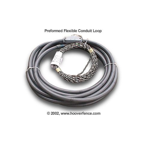
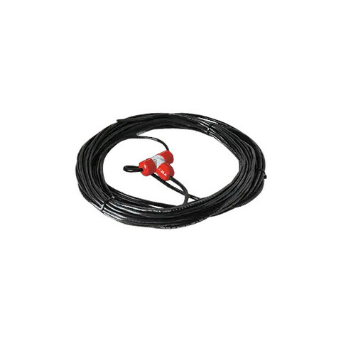
- Requires a loop to make a complete entry/exit device
- One loop detector is required for each function (ie. safety, free exit, free entrance)
Specifications
Specifications
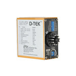
MVP-D-TEK - Specifications (PDF)
| Power Supply | 12VDC to 240VAC |
|---|---|
| Current Consumption | 19.2mA @ 9VDC, 18.8 mA @ 12VAC/DC, 17.3 mA @ 24VAC, 9.5 mA @ 24VDC, 13.5 mA @ 115VAC 11.0 mA @ 237VAC |
| Operating Temp | -40°F to +180°F |
| Surge Protection | Zener Diode /MOV |
| Output Relays (2) | 1Amp 30 VDC |
| Loop Input | Transformer isolation, lightning and transient protection (1) |
| Loop Inductance Range | 20 – 2000 uH Q-factor of 5 or higher |
| Tuning | Automatic on reset or power up |
| Tracking | Automatic for environmental changes |
| Size | Height 3.25” (83mm) Width 2.56” (40mm) Length 3.65” (90mm) |
| Housing | Extruded Anodized Aluminum |
| Connector | 86CP11 11 pin male |
Instructions
Instructions
Videos/Media
Videos/Media
Reviews
Reviews
There are no reviews yet. Be the first to Write a Review (requires login).
Shipping
Shipping
Shipping Expense Disclaimer: All orders are subject to confirmation. Additional shipping expenses, although rare, may apply due to weight, size, location, and/or other variables. Should your order require additional funds to cover the transportation of goods, you will be contacted prior to order processing for approval.
Parts for this product
-
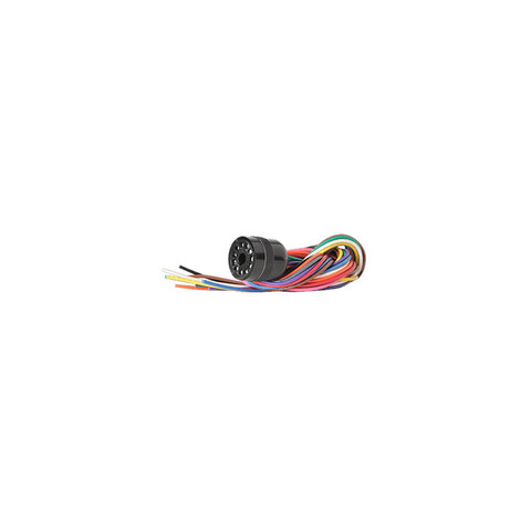
 $149.97EMXVehicle Loop Detector w/Aluminum Housing, and EMX-HAR-11 Wiring Harness#EMX-MVP-D-TEK-BOXKITView More

You May Also Like