
Linear/GTO/Mighty Mule Gate Opener Overview - Operator Tips
Read More: Gate Opener System Overview | Linear/GTO Accessory Diagram
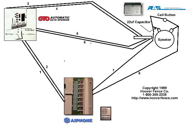
Preliminary wiring:
- 1 Pair from LEM to GTO
- 2 Pairs from GTO to AAS
- 1 Pair from LEM to AAS
- Hoover Fence recommends using 16AWG direct burial wire
- First "EL" on LEM to White lead on GTO/Pro terminal.
- Second "EL" on LEM to Green lead on GTO/Pro terminal.
- Black Wire of AAS Keypad to battery terminal on GTO.
- Red Wire of AAS Keypad to battery terminal on GTO.
- White Lead on GTO/Pro terminal to Orange Wire of AAS Keypad.
- Green Lead on GTO/Pro terminal to Brown Wire of AAS Keypad.
- "1" terminal on LEM to first Call Button Lead on AAS. Split off and run wire to Negative Lead on Speaker with 22uf Capacitor (included with AAS).
- "E" terminal on LEM to second Call Button Lead on AAS. Split off and run wire to Positive Leadon Speaker.
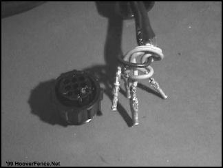
1. First, the wires must be inserted into the plug after you've run the wire through your conduit.
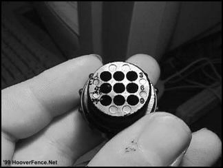
2. Here is how the wires should be inserted: black-#4, red-#1, orange-#3, blue-#6, green-center **NOTE** Some of the holes will be empty.
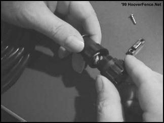
3. Screw the plug back into the cable guard.
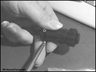
4. Secure the plug to the cable guard with the screws that are provided.
Heddolf Keystone Model P294-K Receiver Installation Instructions
The Heddolf Keystone Model P294-K universal receiver was designed to have several selectable options not found on other radio controls. By properly selecting these options with the convenient slide switches and wiring harness, the Model P294-K eliminates the requirement to stock several receivers.
- The Model P294-K will operate on either 12 or24 Volt AC or DC by selecting either 24V or 12V with the voltage selection switch.
- The Model P294-K will generate either a 0.5 second pulsed, or a continuous relay output depending on the setting of the output slide switch. To energize the output relay as long as the transmitter is activated, select the CONT position. To energize the output relay for 0.5 seconds regardless of how long the transmitter is activated, select the PULSED position. Many gate operators and some garage door operators will not work properly when the switch is in the CONT position.
- The Model P294-K comes standard with 5 wires. Two of these wires (red and black) are for the power input and the other three are the relay contacts. The white wire is the relay common and is always used. Most control circuits require a normally open switch contact. For these applications use the NO (yellow wire) and the white wire. It is recommended that the unused orange wire be cut off. For controls requiring a normally closed switch contact use the NC (orange wire) and the white wire. It is recommended that the yellow wire be cut off if it isn't used.
- The Model P294-K comes standard with an "F" connector and a 1/2 wave wire antenna. If signal conditions require the use of an external coax antenna to eliminate signal blockage due to obstructions, dead spots etc., use RG59 coax to extend the antenna to the remote location. The 1/2 wave wire antenna may be left on the receiver.
Model P294-K Mounting & Connecting Instructions - For Most Garage Door Operators
- Disconnect the power to the operator
- Remove access cover of receiver to gain access to the coding switch and the programming switches.
- Place the voltage selector slide switch in either the 24V or 12V position depending upon the control voltage of the operator.
- Place the output selector slide switch in either the CONT or PULSED position depending upon the operator being used. In most cases either position will work properly.
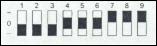
- Set the 9 pole, 3 position coding switch under the access cover to 1 2 3 4 5 6 7 8 9 match the transmitter coding switch. Any switch position will work 0 long as the transmitter coding switch and the receiver coding switch as are exactly matched.
- Mount receiver near the operator so that the wires from the receiver will reach the terminal strip on the operator.
- Connect the black -wire (-V) and the white wire (COMMON) to terminal #1 of the operator.
- Connect the white wire (relay common) to term #1.
- If the operator requires a normally open contact to activate the operator, connect the yellow wire (NO) to terminal #2 of the operator. Cut off the orange wire. If the operator ,requires a normally closed contact, connect the orange wire (NC) and cut off the yellow wire.
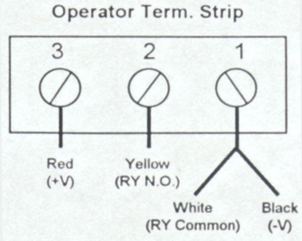
- Connect the red wire (+V) to terminal #3 of the operator.
- Reconnect the power to the operator and test the system. If the distance isn't adequate resposition the antenna for optimum results.
Multi-channel (multi-button) transmitters have only 8 dip-switches for programming instead of 9 as the single button models do. This is because the 9th segment of the transmitter's code is determined by the choice of one of the multiple buttons on the transmitter.
On all GTO and Heddolf-GTO compatible multi-channel transmitters, use of the left button equals a 9th dip-switch setting of "+", use of the middle (or right--on a 2-button transmitter) button equals a 9th dip-switch setting of "0", and use of the right button equals a 9th dip-switch setting of "-". With multi-channel mini-transmitters, this is true when the transmitter is held with the keychain facing you.
Therefore, when you teach your GTO gate operator's control board a transmitter code with a single button transmitter and intend also to use a two-button transmitter with the operator, the 9th segment of the code must be either a "+" or a "0", depending upon which button you wish to use for that operator.
Note that the two transmitter settings illustrated below are identical.
![]()
To use both a one-button and a multi-button transmitter with your GTO gate operator:
Step 1: Teach your GTO gate operator your personal transmitter code.
- On your one-button transmitter, set the dip-switches to your new personal secret code, setting dip-switch no. 9 to "+".
- Turn the power switch on your GTO gate operator off.
- Holding down the S-5 programming button on your GTO control board, turn the power back on.
- Release the S-5 programming button.
- Press and hold your transmitter button until the red light on your GTO control board flashes bright, then returns to dim.
- You have now taught your new transmitter setting to your GTO gate operator, and the operator is in its normal operating mode.
Now your GTO gate operator will work with any GTO-compatible transmitter.
Step 2: Set your 2 or 3 button transmitter to work with your GTO gate operator.
- Set the 8 dip-switches on your 2 or 3 button transmitter to match the first 8 dip-switches of your one button transmitter.
- Press the left button on your 2 or 3 button transmitter. If you have a 2 or 3 button mini-transmitter, hold it with the keychain facing you.
If you have followed the above instructions precisely, your gate will now open.
To use only multi-button transmitters with your GTO gate operator:
- Set the 8 dip-switches on your multi-button transmitter however you like.
- Turn the power switch on your GTO gate operator off.
- Holding down the S-5 programming button on your GTO control board, turn the power back on.
- Release the S-5 programming button.
- Press and hold the left button on your transmitter until the red light on your GTO control board flashes bright, then returns to dim. This is now the button that will open your gate.
- You have now taught your new transmitter setting to your GTO gate operator, and the operator is in its normal operating mode.
Now you can use any 2 or 3 button transmitter with your GTO gate operator. Simply repeat the above steps with your additional transmitters, setting the dip-switches identically to the ones in your first transmitter.
Installation of the Exit Wand
The exit wand should only be buried the minimum amount below the ground yet deep enough to avoid damage to the unit. 3" to 6" maximum is the recommended depth. It need not be buried at all if suitable protection is provided to the unit.It is not necessary to bury it in the driveway, but it will be more sensitive if it is. It can detect vehicles passing at 5 M.P.H. within 12’ of the unit. First try plugging it in and trying it before burying it. Lay it adjacent to the driveway for testing. Adjust it to the distance from the gate as desired. 100’ of wire is typically provided with the unit, but you can locate it anywhere up to the length of the wire.DO NOT open the wand box! It is factory sealed for a waterproof fit. The warranty will be voided if the box is disassembled.
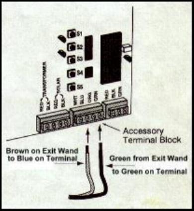
- Connect the Red and Black wires from the Exit Wand to the Terminals on the Battery.
- Connect the Brown wire on the Exit Wand to the Terminal marked Blue on the GTO.
- Connect the Green wire on the Exit Wand to the Terminal marked Green on the GTO.
For additional information: See page 22 (Pro1000), page 17 (SL1000), page 26 (Pro2000) of your GTO Owner’s Manual
Once you have tested the wand to your satisfaction, bury it the minimum distance possible.
DO NOT DRIVE DIRECTLY OVER WAND. IT SHOULD BE PLACED DIRECTLY BESIDE THE DRIVING SURFACE. EITHER BURIED OR SIMPLY LAYED BESIDE THE DRIVEWAY WILL WORK BEST.
Consider that cars could drive off the driveway or other earth disruption could damage the unit. The wire can be buried as deeply as you desire to protect it. Only the wand will detect vehicles.If you feel that disruption of the dirt might occur damaging the wand, place it inside a plastic pipe or under treated plywood to protect it before covering it with dirt.Always test it as you backfill the dirt. The depth of burial can affect its sensitivity.
The EMX D-Tek and the GTO/Pro Gate Operator can be used together for several different functions, and we at Hoover Fence Co. will try and outline the different applications and how the 2 products can be used together. NOTE: Only one function is accessible at a time. You can not use a single D-Tek for free exit AND safety. You will need to purchase another.
FREE EXIT - The D-TEK and a loop and be used to make the gate operator function to open the gate with a vehicle approaches the gate. If the gate is in the open position and begins to close, the activation of the D-Tek box will reopen the gate. If the gate is in the open position and the loop is broken by the path of a vehicle, the gate will not close. To hook the D-Tek up as a free exit/entry device:
| EMX D-TEK | LOOP | GTO/PRO Accessory Terminal |
|---|---|---|
| Pin 1 - White - Power | - | Terminal 1 on battery |
| Pin 2 - Black - Power | - | Terminal 2 on battery |
| Pin 4 - Green - Ground | Uncolored - shield | Ground out in control box |
| Pin 5 - Yellow - Presence Relay Comm. | - | Green |
| Pin 6 - Blue - Presence Relay N.O. | - | Blue |
| Pin 7 - Gray - Loop | Black | - |
| Pin 8 - Brown - Loop | White | - |
SAFETY LOOP - When the loop is broken the gate will remain open or reopen if closing. The activation of the loop will never open the gate when hooked up to these terminals in the GTO/Pro gate operator.
| EMX D-TEK | LOOP | GTO/PRO Accessory Terminal |
|---|---|---|
| Pin 1 - White - Power | - | Terminal 1 on battery |
| Pin 2 - Black - Power | - | Terminal 2 on battery |
| Pin 4 - Green - Ground | Uncolored - shield | Ground out in control box |
| Pin 5 - Yellow - Presence Relay Comm. | - | Orange |
| Pin 6 - Blue - Presence Relay N.O. | - | Green |
| Pin 7 - Gray - Loop | Black | - |
| Pin 8 - Brown - Loop | White | - |